Peavey 5150 Overhaul
Here are some notes on the Peavey 5150 overhaul that we did over the course of two, (or is it three?) videos recently.
What went right:
All electrolytic capacitors were changed on the main board and on the preamp board, pots and jacks were cleaned, adjustable bias was removed, tubes were tested (all had plenty of life) and reinstalled, pot and jack solder joints were re-flowed.
What went wrong:
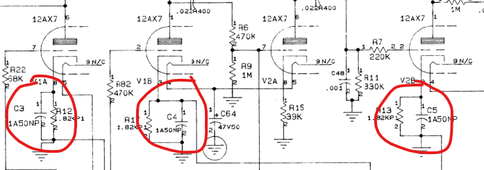
This one had a couple of learning lessons that I hope others can benefit from as well. The three bypass caps on the preamp board (C3, C4, C5) are listed as 1A50NP on the schematic, which means that they are 1uF 50V and NON-POLARIZED. These non-polarized caps look exactly like normal electrolytic capacitors; however, they do not have a polarized sensitivity (positive and negative side) the same way that normal electrolytic caps do! They can be replaced with normal electrolytic capacitors, but the polarity must be accounted for. I ended up installing these new caps backwards because I used the indentation of the cap cylinder as an indication of the positive side of the capacitor but this was WRONG in this specific scenario. This issue caused the sound to fade completely away on the amp once the caps charged up.
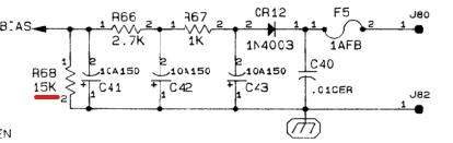
Another issue on this amp was replacing the bias resistor. At some point (maybe 12 years or more ago??) I replaced the bias resistor (R68) with a modification to allow for adjusting the fixed bias of the amplifier. I decided to remove this mod while doing this overhaul repair of the amp. Funny enough, even the modded version of the amp was left at the stock value so at some point in my experiments I found that I liked the stock value here the best anyways. These amps are biased cold, which is not only part of the sound of these amps (distortion comes from the preamp and the power amp simply amplifies that instead of coloring it), but it also means that your power tubes will last waaaaaay longer than they otherwise would! If you do want to perform this mod you simply need to replace the 15K ohm resistor with a 10K ohm resistor that is in series with a 10Kohm potentiometer. The mistake that I made was replacing that mod too late at night and confidently installing a 1.5K ohm resistor instead of a 15K ohm resistor.
Upon firing up the amp at full power the power tubes began to red plate, which means that there is too much voltage at the grid of the tubes, which is also where the bias voltage is applied. I checked out the bias circuit and sure enough, had installed the wrong value resistor for R68: