1973 Fender Champ Tune Up
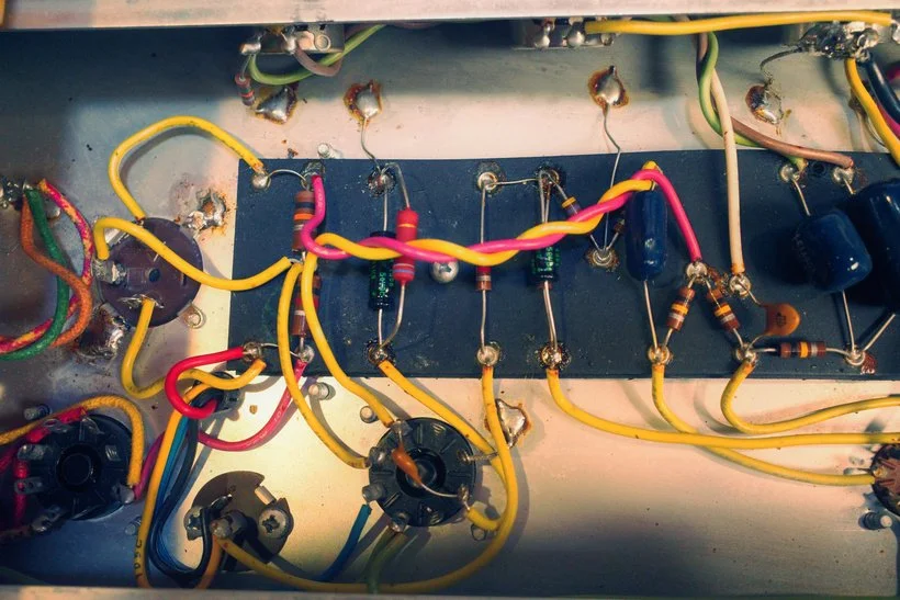
So today we are back in a 1973 Fender Champ that received its initial inspection in early December. This amp arrived on the bench with the warning that it had been dropped at some point and now would power up but there was now sound. The power tube had been changed out but nothing else had been done to the amp to troubleshoot.
On that initial inspection I found that the amp actually DID have sound coming out of it. However, the volume pot had been replaced at some point, and the new one was installed backwards, so at a volume of 10 there was no sound and at a volume setting of 0 there was max volume. This amp otherwise had all original filter caps and components, as well as a very frayed power cable. The customer asked for the "full service" and parts were ordered to make that happen!
The volume pot was replaced with a 1MA (1 Mega-ohm, audio taper) CTS pot with a smooth as can be taper. I also replaced the cathode bypass caps with Sprague 25uF 50V and 2uF 50V to match the original values in the amp, and replaced the can multi-section cap with an equivalent one from CE Distribution.
The real trick with these amps is that the power at the 6V6 power tube is MUCH higher than it should be. The schematic calls for 350V at the Plate and 19V at the cathode. That is 311V across the tube at idle. With modern wall voltages and stock components we will be MUCH higher than that!
So, one action that can be taken to lower that voltage across the tube is to raise the value of the 470 ohm 1W resistor that is at the cathode of the power tube. Raising that resistance means more voltage is dropped across that resistor. Dropping more voltage across that resistors means the voltage at the cathode will be higher, which means LESS voltage will be dropped across the tube between the Plate and Cathode.
Adjusting that resistor to a 680 ohm 3W Vishay Metal Oxide resistor left the amp at idle with the following voltages:
433 on Plate
428 on Screen
30.53 on Cathode
This is a voltage of approximately 400V at idle across the tube which is STILL higher than ideal conditions but much better than if we had not raised the value of the cathode resistor.
This amp also had a fused neutral wire for the power section which is not good for safety so I went ahead and rewired the power cable to ensure that the "Hot" of our AC power first went to the back of the fuse holder, left the fuse holder to the power switch, then connected to the transformer primary winding. The other side of the primary winding is then connected directly to the neutral of the power cable. Earth ground, as always, is left longer than the other hot and neutral and is given a dedicated chassis ground connection.