1966 Fender Super Reverb Overhaul - Part 1
We are BACK in the 1966 Fender Super Reverb barn find that a customer brought in. This amp has some issues with powering on and the customer has agreed to getting it operational as a gigging amp while still respecting that it is a PRISTINE and untouched 1966 black panel Fender. We are going to change as little as possible while still getting this thing reliable for gigs and regular playing. So the real question is, how do you approach something like that?
Filter Caps - These are basically wear and tear items for amplifiers and electronics in general. All electrolytic capacitors have a shelf life of approximately 20 years due to the nature of the electrolytic material in them drying up over time. The ones in this amp are roughly 60 years old at this point!! They not only need to be removed, but ALL need to be removed (this is not something to do as one off replacements), to ensure stability and longevity of the amp. You can think of these components as being like the tires on your car, and more specifically tires on an all wheel drive car. If one tire goes bad, you have to replace them all, because otherwise you are putting more stress on the remaining old tires. The same principle applies here. If you only change out the obviously failed filter cap, the other remaining ones will be under more stress than they were before.
Carbon Comp Resistors on Power Board - These resistors are simply not well suited for being under the stress they endure in this location due to heat. The temperature coefficient of carbon composition resistors is such that their resistance value will change drastically when they heat up. That is NOT a good feature for a resistor in a power supply location where we want things to be as stable as possible. Replacing these resistors with comparable value Metal Oxide, Flame Proof, resistors is the best move while we have the board apart.
Bias cap and resistor - The same principles as above also apply to both the bias capacitor (another electrolytic cap that is well beyond it's life span), and the associated resistor (also is a carbon composition resistor where a Metal Oxide would be a better choice). The only other difference here is that we should definitely raise the voltage value of the bias capacitor from the stock 50V to a more appropriate 100V. You can also opt for a 100uF capacitor, or stick to the stock 50uF. The higher value will stiffen up the filtering slightly, but honestly you will probably not notice the difference between the two either way.
Cathode Bypass Capacitors - These again are replaced under the same principles as the other electrolytic in the amplifier. We stick to the stock 25uF value for these capacitors unless you are wanting to do some tone tweaking. But the voltage level is raised to 50V simply because capacitors at that value are easier to find.
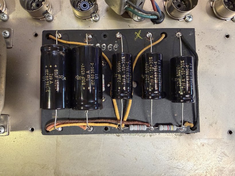
New Caps and Metal Oxide Resistors Installed
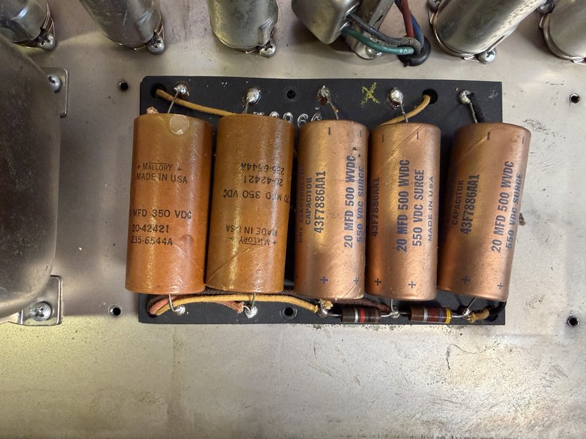
Original Filter Caps and Carbon Composition Resistors
So what was all of that talk about balance resistors about?
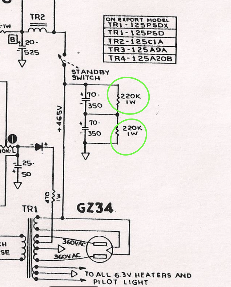
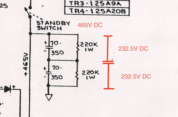
These two 220K, 1W, resistors are what we call "balance" resistors. These are the resistors that form a voltage divider, alongside your first stage of filter capacitance, and act as a way to "balance" the voltage split between the two filter caps that are in series. Okay, so but WHY are there two capacitors in series? Well, back in the 60s when these amps were designed it was very hard to manufacture capacitors at the capacitance and voltage needed for the values in this position. Because of that TWO capacitors at a smaller voltage were used, with each splitting the voltage across them (remember that voltage is split for components in series with each other).
The only issue here is that capacitors are not intrinsically resistive devices. While they do have a small amount of resistance, which we call ESR (Equivalent Series Resistance), this is not a fundamental property but instead a side effect of capacitor imperfections that will change over the life of the cap. In order to ensure that the two capacitors have a much more stable, and similar, voltage across each of them we use the arrangement shown above. Because components in parallel with each have the SAME voltage, the resistors will force an equal split of the voltage as series components, and then will share that same voltage across each capacitor that each individual resistor sees.
Part two will cover the rest of the overhaul of this amp including Bias cap and board updates, cathode bypass cap updates, fixing the tremolo circuit, replacing screen resistors, and adding a new power cable. Until next time!