Peavey VTM 60 | Full Rebuild Part 2
Okay, this one is going to require one more video to get things wrapped up. But we still made good progress tonight getting the Power Tube PCB and the Preamp Tube PCB in good enough condition to move forward. I still am tempted to basically pull all of the PCBs in this amp and redo the whole thing with turret boards... maybe if i ever get caught up on the rest of my amps then I will take the time to do that! Lots of lifted and broken traces on the PCBs in this thing from prior repair work, but we are gonna make the best of it for now!
Okay, starting off, i had to go ahead and remove the Sharpee markings from the prior tech that had left his mark(er) here. A little isopropyl alcohol made quick work of erasing his legacy.
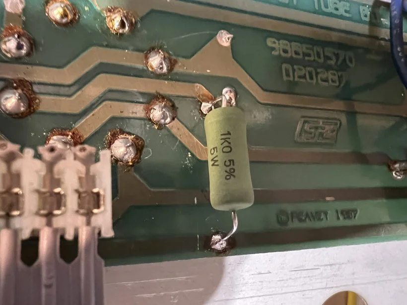
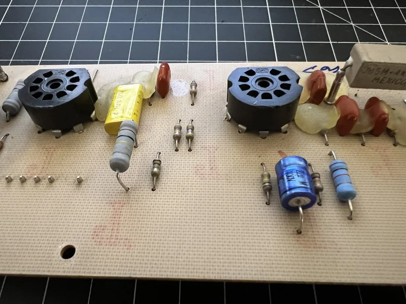
Next up was replacing the screen resistors. I put in Vishay 1K ohm 5W resistors. These are lighter than the concrete block style ones so they support themselves by their legs a little better and are all around just better performing resistors. Stock value in these amps for screen resistors is 100 ohms (same as in the original 5150 amps). For the longest time i stuck by the argument of sticking to the stock value for resistors here... but I am coming around to the idea of higher resistance. Fenders use 470 ohms, Marshalls use 1.5K ohms in this same position. The higher resistance protects the tubes more and at this point in my life I doubt i could hear the sound difference. At some point I will do a video swapping out values between the three and will upload high quality sound samples of each for people to compare. But today is not that day.
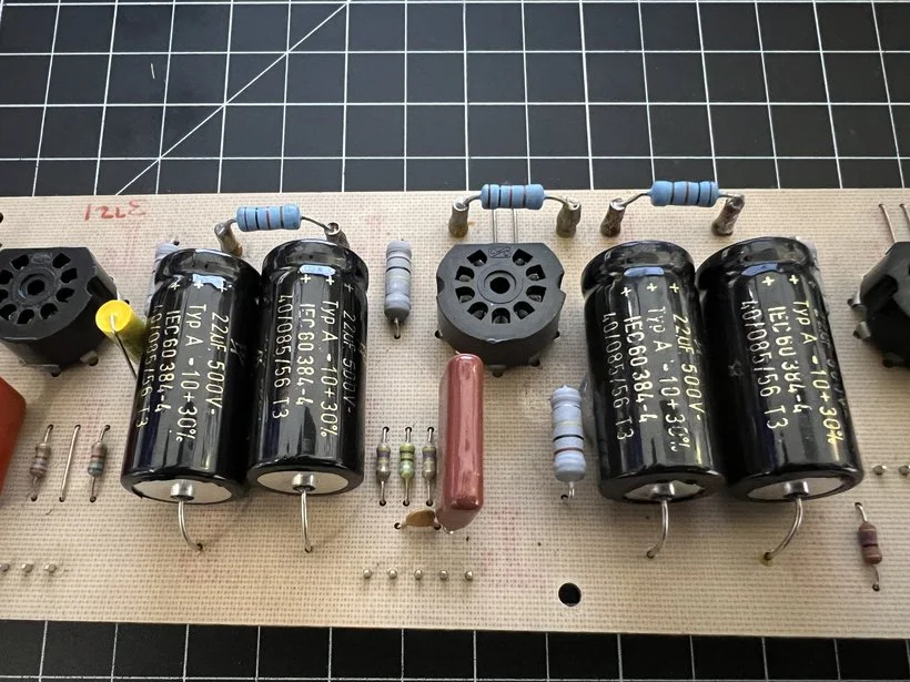
Next up was changing the electrolytic caps on the preamp tube PCB. The new black caps are F&T brand and all are 22uF 500V, which is the stock value for these caps. The small blue one is a 22uF 50V as the stock value. I replaced it with a 22uF 100V from the drawer.
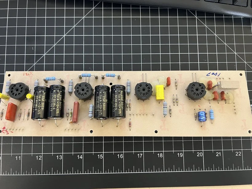
I also replaced all six 100K ohm metal oxide plate resistors on this board since they seemed a little toasty. Plate resistors are a very common point of trouble in amps since they see a lot of power dissipation and also can inject noise into your signal if they are starting to go out. If you have an amp with original plate resistors and are starting get mysterious crackling, hum or other background noise that can't be traced back to power caps, tubes, or screen/grid resistors at the tubes, the plate resistors are the next most likely place to look. Since i was in here and am doing an "overhaul" of this amp I went ahead and changed them out.
This plate resistor will live an elevated life since it was slightly too long for the footprint. But that's okay. More room off of the board means more air flow and easier heat dissipation.
At this point I had to cut the video short (at the 60+ minute mark - wait, is that short??), because i am still getting over a cold and my voice was starting to give out a bit. So what is left to do? Well, i need to remove this switch that seems to toggle between two resistor setups for the first gain stage, one with a bypass cap on it (will trace this out better for the next Patreon post).
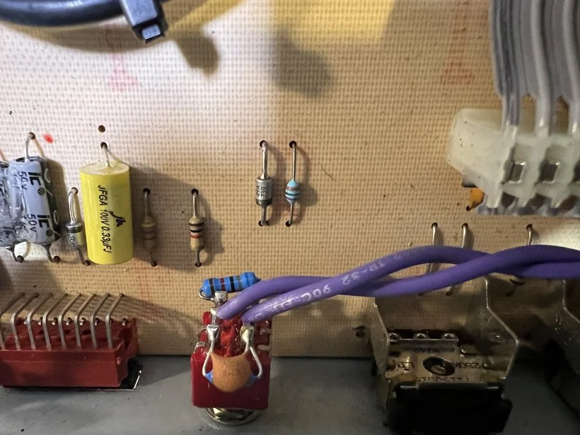
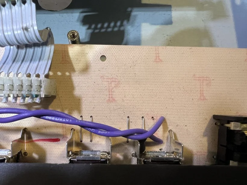
And last of all will need to clean up this mess of a tack solder at best and an electrical tape holding wires in place situation at worst, before putting everything back together and powering this thing back up!
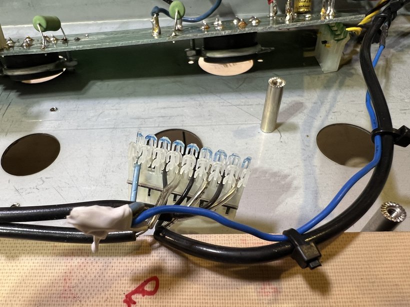
No parts list this time around, but I will add a final parts list to the next post when we wrap this project up! See ya on the next one!